


The VOR
CPL Assist
The VOR is one of the basic radio navigation aids (along with the ADF) that you are expected to understand
thoroughly when flying as a new Commercial pilot. This is because most aircraft, regardless of size, are
likely to be equipped with, at least an ADF, and most probably a VOR. As a result your knowledge of the
two systems will allow you to reach your destination, or an alternative safely and without the need of other
aids.
You will be taught to use the VOR during your instrument rating practical training and you will find it a particularly precise and somewhat easy method of staying on a track. Even the process of intercepting a track will be quickly mastered.
You will then sit in the CPL ground school classroom and wonder why the example exam questions are so confusing. The answer is in what is not taught in the practical lessens, and which is the core of what the exam questions are designed to test.
What is this magical knowledge that will get us through the exam?
Believe it or not, The VOR system has no knowledge of your aircraft’s heading.
To many people this is a surprise seeing as, when using the VOR for practical flying, it gives a TO indication when flying to the beacon and a FROM indication when flying away. This would suggest, even to the keenest minds, that the system knows your direction. In actual fact, it gives the logical information only because you are using it correctly; i.e., your heading is the same as your chosen radial. That is the rule your instructor gives you and it is one to remember always.
That’s ok for the practical flying but here is the description of the VOR taking into consideration the exam questions:
The VOR Beacon
This drawing is a simple representation of the signal pattern set up by the VOR beacon. It can be
thought of as producing 360 radial ‘great circle’ tracks away from the beacon, each with 1°of
separation from the next. I have drawn an arrow head at the end of each radial to signify that the radial
can be though of as carrying the direction.
The VOR Course Deviation Indicator (CDI)
The VOR Course Deviation Indicator (CDI)
This picture shows one of many styles of CDI. It consists of a compass card which is able to be rotated.
The card is rotated by turning the Omni Bearing Selector (OBS) knob seen at the bottom left. When turned,
a required radial / bearing can be set against the yellow marker at the top of the dial. On this CDI the chosen
OBS selected radial is also displayed electronically above the dial. When the pilot selects a bearing, he/she is
telling the system which radial represents the course that he/she wants to track.
In this case (this picture), the pilot has selected the 345° Radial. As a result the system will set up a pattern around the chosen radial as follows:
In this case (this picture), the pilot has selected the 345° Radial. As a result the system will set up a pattern around the chosen radial as follows:
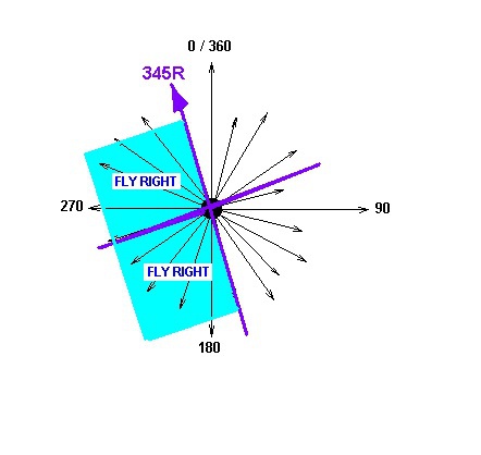
This pattern (the purple cross) covers the physical space around the beacon on the earth for as far as the
signal can be received. The actual OBS selected radial (345) defines the position of the cross pattern. The
cross divides the space into 4 quadrants. The quadrants are named using the terms TO, FROM, FLY
LEFT, and FLY RIGHT.
FROM and TO
The two quadrant which lie on either side of the 345 radial are named the FROM quadrants because an aircraft flying in the direction of the OBS selected radial, if it were in either of those quadrants, would be moving away from the beacon.
FROM and TO
The two quadrant which lie on either side of the 345 radial are named the FROM quadrants because an aircraft flying in the direction of the OBS selected radial, if it were in either of those quadrants, would be moving away from the beacon.
Likewise, The two quadrant which lie on either side of the reciprocal of the 345 radial are named the TO
quadrants because an aircraft flying in the direction of the OBS selected radial (345), if it were in either of
those quadrants, would be moving closer to the beacon.
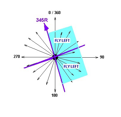
Fly Right / Fly Left
Using the same thought process, when looking along the chosen radial from the reciprocal end in the direction of the arrow on the radial, any aircraft on the left of the radial would have to fly right to intercept the radial or it reciprocal and therefore: the two quadrants on the left are named: FLY RIGHT.
Using the same thought process, when looking along the chosen radial from the reciprocal end in the direction of the arrow on the radial, any aircraft on the left of the radial would have to fly right to intercept the radial or it reciprocal and therefore: the two quadrants on the left are named: FLY RIGHT.
And finally, on the same basis, the two quadrants on the right are named the FLY LEFT quadrants.
The result of this exercise is a double-barrelled name for each quadrant, as follows:
It is the position of the aircraft in this pattern which drives the CDI indicators.
Remember that the pattern as shown here is for this specific radial. If a different radial was to be selected on the OBS the pattern would rotate to a position astride the new chosen radial.
The CDI Position Indicators
Let’s take another look at the CDI:
Remember that the pattern as shown here is for this specific radial. If a different radial was to be selected on the OBS the pattern would rotate to a position astride the new chosen radial.
The CDI Position Indicators
Let’s take another look at the CDI:
TO / FROM
In this picture you will see a small triangular pointer to the right of centre. It is currently in the TO position. On many CDIs it would actually show the word TO. If the triangular pointer was pointing down, it would be in the FROM position. The indication will show TO if the aircraft is in one of the TO quadrants and would indicate FROM if the aircraft was in one of the FROM quadrants.
NOTE: The indications react only to the position of the aircraft and not to the direction of travel of the aircraft. To exaggerate this fact;: if the aircraft was practicing a ‘spin’ in the TO quadrant of the pattern, the CDI would show TO.
FLY LEFT / FLY RIGHT
In the same picture a needle is shown hanging down from the top centre of the CDI. The pilot should envisage it as the chosen radial. If the aircraft is on the radial or it’s reciprocal, the needle will settle in the middle. The needle in that case would be over the centre dot and over the central dot of the arc of dots which sweep from left to right across the bottom of the CDI.
If the aircraft is in a Fly LEFT quadrant, the needle will swing to the left. The pilot should envisage the aircraft to be represented by the central dot. If the needle is to the left, the pilot is receiving a FLY LEFT indication, meaning that to get to the radial he/she would turn to the left.
Likewise If the Aircraft was in a FLY RIGHT quadrant, the needle would shift to the right and the pilot would have to turn to the right to get onto the radial.
Again it must be stressed the needle goes to the left if the aircraft in a FLY LEFT quadrant. Only if the aircraft was heading in the direction of the chosen radial, would the radial actually be on the left of the pilot (think about the previous example of an aircraft practicing a ‘spin’, the same applies. If the aircraft is spinning in the FLY LEFT quadrant, the needle will give a FLY LEFT indication.
WHAT IS THE ARC OF DOTS FOR ON THE CDI?
The ark of dots which the needle sweeps through indicates the number of degrees your aircraft is away from the chosen radial or its reciprocal. A swing of the needle to the last dot represents an indication that the aircraft is 10° away from the radial. This indicator and most modern instruments have 5 dots in each direction. Some systems have 4 dots and some have 2 either side. Regardless of the number of dots, the last dot represents the 10° position. For this 5 dot instrument, each dot will be 2°. The 2 dot instrument would register 5° per dot, etc..
Exam Questions
As I mentioned earlier, the exam questions test your understanding of the fact that the CDI indications are based on your aircraft’s position in the pattern around the OBS selected radial and not (NOT) the aircraft’s direction.
The questions will give you two pieces of information:
The OBS selected radial.
The position of the aircraft.
When you read a VOR question, look for these two things. When found, start by drawing the OBS selected radial and sketch the pattern as I have described it here.
Take the following example:
Q. The pilot has selected 040° on the OBS. The aircraft bears 350° from beacon, and is heading 170° Magnetic.
What are the CDI indications?
a) Fly Right /To b) Fly Right/ From c) Fly Left / To
Answer: I first note that I have been given the two vital pieces of information. I always start with the OBS selected radial about which I draw the pattern as follows:
Now I can place the Aircraft into the pattern. The aircraft is on a bearing of 350 from the beacon. Be
careful here because the word ‘from’ which I have just used has nothing to do with the TO / FROM of the
pattern. It is simply a way of expressing where the aircraft is in relation to the beacon.
I have drawn the aircraft as a cross so as not to be swayed by the aircraft’s direction. It can be seen that the
aircraft is in the From / Fly Right quadrant, therefore b) is the correct answer.
NOTE: The heading has no effect on the answer. If I had drawn the aircraft heading 170°, I may have been tempted to assume that, because the aircraft was heading to the beacon, the CDI would recognise this and indicate TO. Remember that the VOR does not know which way the aircraft is heading and only works with the quadrants as defined by the OBS selected radial.
The Position of the Aircraft
In the above case, the position of the aircraft was given in a fairly simple way by the phrase; bears 360 from the beacon. Look out for this method. They may also use the term: ‘ is due West of the beacon’. Due can be replaced by True.
A method which is somewhat more complex and confusing is when the question refers to the phase difference between the two transmissions of the VOR beacon. To explain this, I will have to describe how the signal is sent.
The VOR Beacon Signal
The VOR beacon transmits two separate signals; One called the reference signal and one called the Directional or Variable signal (I’ll reference to it from here as the Variable signal)
The Reference Signal – This is an omni-directional transmission which acts like the result of dropping a pebble into a smooth pond. The waves travel from the point of impact in a circular pattern. The diagram below shows two wavelengths.
This signal is more complex than it looks in that it is generated by first creating a 9960 Hz sub-carrier on the
VHF frequency and then modulating the sub carrier frequency at 30Hz. For most questions it is sufficient to
call it a 30Hz frequency modulated signal. Just remember the ‘9960 Sub carrier’ in case it is mentioned in the
question. In effect it is creating a wave every 1/30th of a second (30 waves per second).
The Variable Signal – This signal is generated by rotating a directional signal through the full 360°, 30 times per second (once every 1/30th of a second). It is difficult to imagine what effect this would have on the resulting transmission when considering something that is happening so fast.
To picture the result I use the comparison of a garden hose streaming water in one direction. I then imagine rotating the hose around my head and start to see that the water would take up a spiral pattern with the spiral traveling outward. Each 360° swirl of the spiral would pass a stationary object on every turn.
This is in fact what will happen with the radio signal. The waves of the spiral would pass the aircraft receiver every 1/30th of a second. The wave form is said to equate to a 30Hz amplitude modulated signal. It is to be an ‘apparent’ amplitude modulated signal. It is sometimes said to have the ‘characteristics’ of an amplitude modulated wave. The graphic below shows one wave length of the reference signal with the spiral of the variable signal superimposed.
In this picture we can see the comparison between the Variable and the reference signal.
At the 0/360 position the variable is keeping up with the reference. This is because the variable signal was pointing in that direction at the beginning of this cycle.
At the 90 position, the variable can be seen to be lagging behind the ref by a quarter of a wavelength. This is because the variable signal had to physically rotate to the 90 degree position before the signal went in that direction. A quarter of a wavelength is 90° of phase. We can see that the variable signal lags behind the reference signal and that when it lags by 90° it must be on the 90 radial.
The same applies with the 180 position. The variable is lagging behind the reference by 180° of phase, and this happens on the 180 Radial.
One can conclude then, that if you measure the phase difference between the Reference and Variable signals and the variable lags the reference, the phase difference is equal to the radial on which the aircraft is.
Why did I add the word lag?
The answer is that the questions talk about the two signals lagging or leading. The basic theory that I have covered here assumes that the VOR receiver has picked up two signals from the same cycle. I.e., the variable signal started to rotate when this reference signal started to be transmitted from the beacon. In practice the receiver could pick up the reference signal for this cycle and the variable signal from the previous one as in the following picture:
You can see in this picture that the phase comparison is being done between the inner reference and the
outer (blue) variable signal. The result is that the phase difference is ¾ of a wavelength or 270° at the 90
position.
The VOR receiver overcomes this by checking which signal is leading and which is lagging.
Rule 1. If the Reference signal leads the Variable signal then the phase difference = the radial.
Rule 2. If the Variable signal leads the reference signal then the phase difference has to be subtracted from 360° to calculate the radial.
These are the rules that the system uses and are the same rules that you should use to position the aircraft in questions which give the phase difference.
Example Question
Q. The pilot has selected 146°on the OBS. The Reference signal leads the Variable signal by 142°. The aircraft is heading 300°magnetic.
What CDI indications will the pilot be receiving on a 5 dot indicator.
a) 4 dots Fly Right / To b) 2 dots Fly Right / From c) 2 dots Fly Left / To
The first thing I see is that I have an OBS selected radial. I can draw the Pattern around its direction.
Now I have to place the aircraft. By using the phase difference, I start by checking against the rules and
find that this is rule 1, the reference leads the variable by 142°, therefore the Radial that the aircraft is on is
142. Next I draw the aircraft position.
We can see that the pilot will be receiving ‘From / Fly Right. The number of dots will be 2 because it
142° is 4° from 146° and the 5 dot indicator indicated 1 dot per 2°. b) is the correct answer.